UniFi Installation Challenges: 6 Common Problems & Solutions (2026)
Learn the 6 most common UniFi installation challenges and proven solutions from 100+ business deployments. Covers firmware compatibility, PoE planning, cabling issues, and more.

Key Takeaway
Successful UniFi deployments require validating firmware compatibility, calculating total PoE budgets using maximum device ratings, and verifying cable infrastructure before mounting equipment.
We have analyzed over 100 business deployments to identify the recurring patterns that stall installations. This guide covers the six most common failure points—from firmware mismatches to power budget overloads—and provides the prevention strategies used by professional installers in 2026.
Affiliate Disclosure: This article contains affiliate links. If you make a purchase through these links, we may earn a small commission at no extra cost to you.
Pre-Installation Planning Framework
Successful UniFi installations require comprehensive planning that addresses infrastructure requirements, equipment compatibility, and implementation logistics. Three critical assessments address most deployment challenges before they occur:
Site Survey: Document existing infrastructure, measure rack dimensions, test cable runs, and identify potential obstacles. This 2-3 hour assessment significantly improves installation efficiency.
Equipment Compatibility: Verify firmware versions, power requirements, and physical specifications. Maintain a compatibility matrix to prevent deployment issues.
Implementation Documentation: Create diagrams showing cable routing, power distribution, and device placement. These serve as planning tools and reference materials for future maintenance. For detailed network planning guidance, see our small business network setup guide.
How Do I Prevent UniFi Firmware Compatibility Issues?
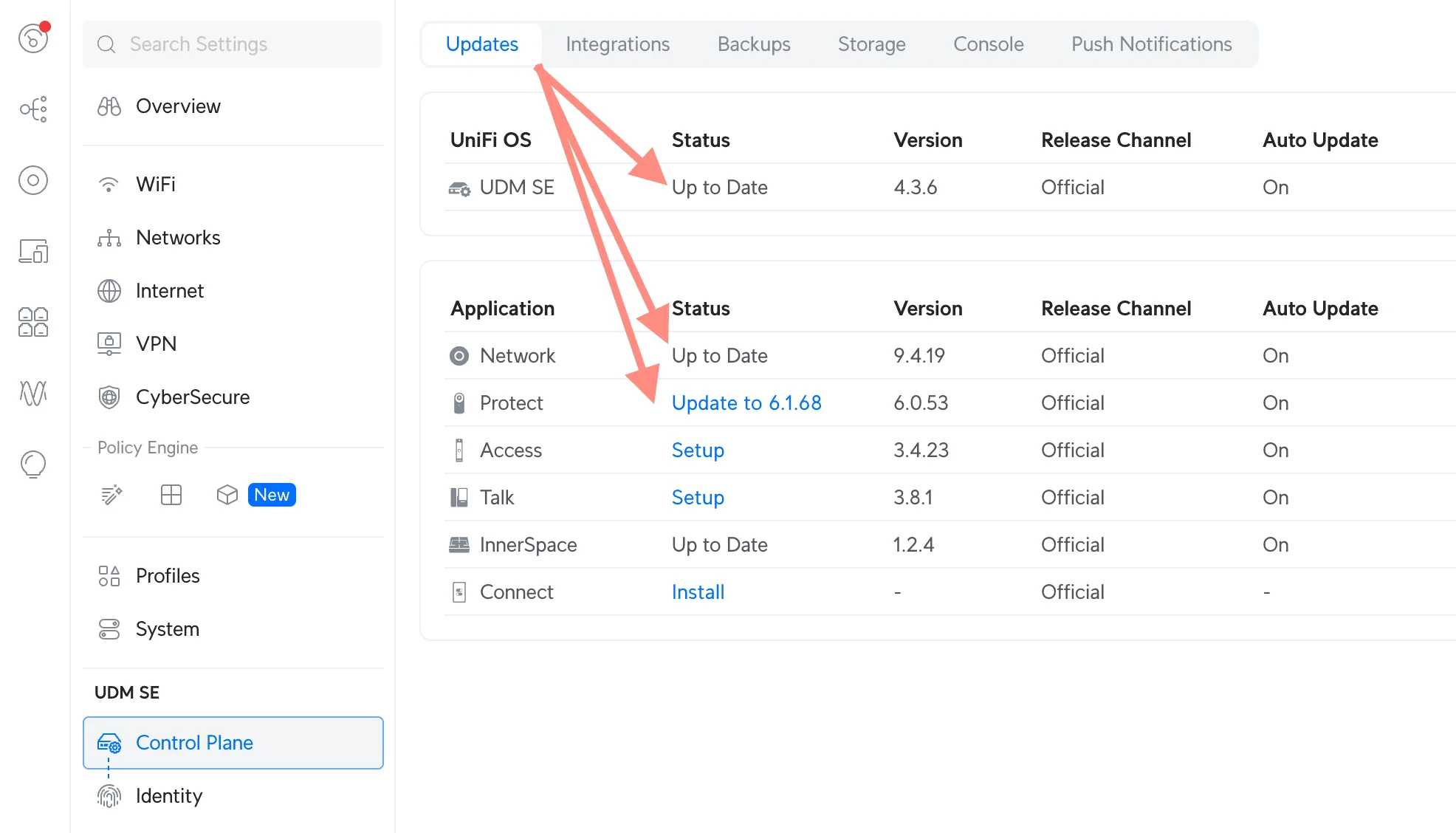
Prevent firmware mismatches by adopting a sequential update workflow—updating the gateway first, followed by the core switch, and finally the access points—before physical installation.
Devices purchased from different suppliers often arrive with varying firmware versions, leading to adoption failures. A UniFi Cloud Gateway Ultra may run a newer Network Application than the factory firmware on a Pro Max 48 PoE switch, causing communication errors. For help choosing the right gateway, see our UniFi gateway comparison guide.
The Sequential Update Protocol
Gateway Selection & Preparation
2026 Cloud Gateway Lineup:
- Cloud Gateway Max: 10Gbps WAN throughput, ideal for fiber connections 1Gbps+
- Cloud Gateway Ultra: 3.5Gbps WAN, compact form factor for small offices
- UDM Pro Max: All-in-one with Protect NVR and 10Gbps capabilities
Learn more about selecting the right gateway in our Cloud Gateway alternatives guide.
Connect only the gateway device to power and the internet. Access the controller interface and complete all available firmware updates to Network 9.x. Gateway updates typically require 15-20 minutes.
- Gateway First: Connect and update the gateway (e.g., UDM Pro Max) to the latest stable release (Network 9.x).
- Core Infrastructure: Adopt and update the main distribution switch.
- Edge Devices: Connect access points one by one to verify stability before mass deployment.
This staged approach identifies compatibility issues early when they're easier to resolve. Once foundation devices are stable and updated, additional access points, switches, and cameras typically adopt smoothly.
Why Are My UniFi Devices Negotiating at 100Mbps?
UniFi devices default to 100Mbps (FE) link speeds when physical cable terminations are damaged, improperly seated, or when using legacy CAT5 cabling that cannot support Gigabit frequencies.
This issue is rarely a software configuration. It indicates a physical layer failure. Even new cable runs can fail if the terminations (keystones/plugs) are not rated for the specific cable type (e.g., using CAT5e plugs on CAT6a cable).
Validation Step
Before mounting APs, test every run with a verifier like the Klein Tools VDV Scout Pro 3 ($200) to confirm wire mapping and continuity. For WiFi 7 (6GHz) uplinks, ensure cabling is CAT6a to support 2.5GbE negotiation.

How Do I Calculate the PoE Power Budget for UniFi?
Calculate the total PoE budget by summing the maximum power consumption listed in the datasheet for every connected device and adding a 20% safety buffer for startup surges.
A common error is assuming switch port counts correlate with power capacity. For example, a deployment with 12 U6 Pro APs (13W max each) and 20 G5 Bullet cameras (4W max each) creates a total potential draw of 236W. For camera selection guidance, see our UniFi Protect security system guide.
- Calculation: (12 × 13W) + (20 × 4W) = 236W maximum draw.
- Real-World Usage: Actual consumption is typically lower—U6 Pro devices often draw 6-9W under normal load, and G5 Bullets average ~3.3W.
- The Risk: While a standard Pro 48 PoE switch (600W budget) handles this easily with 60% headroom, the real concern is inrush current during power restoration after an outage, when all devices boot simultaneously.
- The Solution: For high-density WiFi 7 deployments (e.g., U7 Pro Max at 25W), upgrade to Pro Max series switches which offer both power headroom and Etherlighting for simplified cable management.
PoE Device Power Classifications
Power Standards Reference
Standard PoE (802.3af): Up to 15.4W
- Basic access points like the U6 Lite
- Simple IP cameras without heating elements
- Basic VoIP phones and desk accessories
PoE+ (802.3at): Up to 30W
- Most UniFi access points, including U7 Pro, U6 Enterprise
- PTZ cameras and high-power surveillance devices
- Advanced IP phones with video capabilities
PoE++ (802.3bt): Up to 60W
- UniFi Access Hub, like the UA-Hub-Door
- High-power PTZ cameras with heating/cooling
- Specialized devices requiring maximum power delivery
Practical Power Consumption Data
Field testing shows actual consumption typically stays within specification ranges. The U6 Pro consumes up to 13W maximum under full load, while the newer U7 Pro requires up to 21W and needs PoE+ capable ports. The high-power U7 Pro Max with its 8 spatial streams requires PoE+ for its higher power demands.
AI Camera Power Considerations: UniFi's AI-enabled cameras (AI Theta, AI Pro) consume significantly more power than standard bullets due to onboard processing. The AI Pro can draw up to 12-15W, making them comparable to high-end access points in power planning.
Switch Selection Guidelines
For Small Deployments (8-16 devices): The Lite 16 PoE switch provides 45W total budget, suitable for 3-4 U6 Pro access points (13W max each) or 8-10 U6 Lite devices (8W max each). Calculate actual power requirements rather than assuming maximum port utilization.
For Medium Deployments (16-32 devices): The Pro Max 24 PoE switch offers a 400W budget and can reliably power 16-18 U6 Pro access points. It also provides PoE++ ports for future WiFi 7 upgrades.
For Large Deployments (32+ devices): Multiple switches are often more cost-effective than single high-capacity units. Two Pro Max 24 PoE switches provide 800W total budget with better redundancy than a single 48-port unit.
Etherlighting: Visual Cable Management
Pro Max series switches include Etherlighting—programmable LED indicators on each port that simplify cable identification during installation and troubleshooting. This feature addresses one of the most common physical installation challenges: identifying which cable connects to which device in dense deployments.
Practical Applications:
- Color-code VLANs: Assign blue LEDs to guest network ports, green to management, amber to cameras
- Locate ports remotely: Trigger port LEDs from the UniFi controller to identify cables without physical labels
- Troubleshooting: Quickly identify which port a problematic device is connected to
For installations with 20+ devices, Etherlighting can save hours of cable tracing and reduces the risk of accidentally disconnecting the wrong device during maintenance.
What Is the 2.5GbE Bottleneck for WiFi 7?
WiFi 7 access points like the U7 Pro Max can deliver multi-gigabit wireless speeds, but most existing network infrastructure only supports 1GbE uplinks, creating a performance bottleneck.
The U7 Pro Max supports theoretical wireless speeds exceeding 10Gbps across its 8 spatial streams. However, if connected to a standard 1GbE switch port, total throughput is capped at 1Gbps regardless of wireless capabilities.
Infrastructure Requirements for WiFi 7
Cabling: CAT6a or better is required to support 2.5GbE and 5GbE speeds. Legacy CAT5e cabling maxes out at 1GbE and cannot be upgraded without complete re-cabling. For new installations, consider bulk CAT6a cable for future-proofing.
Switch Compatibility: Standard UniFi switches with 1GbE ports cannot leverage WiFi 7 performance. Upgrade to switches with 2.5GbE or 10GbE uplink ports:
- Pro Max 24 PoE: Includes 2.5GbE ports for WiFi 7 APs
- Pro Aggregation: Provides 10GbE SFP+ ports for maximum throughput
Planning Tip: If deploying WiFi 7 in 2026, budget for both the access points AND the switch infrastructure to support multi-gigabit uplinks. Otherwise, you're paying for performance you cannot utilize.
WiFi 7 Compatibility Note: WiFi 7 access points (U7 series) require WPA3 encryption and may have compatibility issues with legacy IoT devices that only support WPA2. Test device compatibility before full deployment, especially with older printers, smart TVs, and building automation systems.
What Rack Depth Do I Need for UniFi Switches?
Physical installation challenges often become apparent during equipment mounting. Rack depth limitations, cable management requirements, and ventilation needs can create constraints that weren't obvious during initial planning.
These issues are common in older office buildings where existing network closets were designed for simpler equipment. Modern UniFi switches require more depth and ventilation than legacy equipment.
Common Space Constraint Example
Consider a scenario where a UniFi Pro 48 PoE switch (15.7" deep) is specified for a deployment, but the existing wall-mount rack provides only 14 inches of usable depth. The switch physically won't fit, and adding power cables and network connections requires an additional 2-3 inches of clearance.
This situation requires rack replacement, equipment relocation, or switching to a 24-port model. If not identified during the initial planning phases, these changes can add 1-2 weeks to project timelines and $500-$1,500 in unexpected costs.
Rack Depth Assessment
Standard network racks vary significantly in internal depth. Wall-mount enclosures typically provide 12-15 inches of usable depth, while floor-standing racks offer 24-30 inches. However, cable management, power distribution, and ventilation requirements reduce effective depth.
Measuring actual usable depth accounts for:
- Rear cable management space (2-3 inches)
- Power cable clearance (1-2 inches)
- Ventilation requirements (1-2 inches minimum)
- Front panel accessibility needs
Power Protection: Don't forget to budget for a quality UPS system to protect your network equipment from power fluctuations and outages.
UniFi Switch Depth Specifications
Critical Measurement: Many installers overlook switch depth requirements, leading to last-minute rack replacements. Always measure total usable depth (rack depth minus cable management space) before ordering equipment.
Compact Switches (12-16 ports): The Lite 16 PoE measures 7.6 inches deep and fits most wall-mount enclosures. These switches work well for small office installations where rack space is limited.
Standard Switches (24 ports): The Pro 24 PoE switch requires 11.2 inches of depth and represents the practical limit for wall-mount installations. Proper cable management requires additional 3-4 inches of clearance.
Large Switches (48 ports): The Pro 48 PoE switch extends 15.7 inches and requires substantial rack depth. Many "shallow" wall-mount racks provide only 12-14 inches of usable depth, making them incompatible. This switch works best in floor-standing racks with 24-30 inches of total depth to accommodate cables and ventilation.
How Do I Prevent Single Points of Failure in Multi-Floor Networks?
Network extensions to additional floors or buildings create single points of failure that can disrupt operations if connectivity is lost. For businesses occupying multiple floors, a single cable failure can affect entire sections of the organization. Building maintenance, renovations, or infrastructure changes can damage critical network connections.
Redundancy Planning Example
Consider a medical practice occupying two floors where the connection between floors uses a single Category 6a cable through shared building conduit. While this connection may work reliably for extended periods, building maintenance or tenant improvements could damage the cable.
The repair process requires building management approval and contractor coordination. Implementing redundant connectivity during initial installation is typically more cost-effective than addressing outages after they occur.
Redundancy Implementation Strategy
Multi-floor installations benefit from redundant connectivity that prevents single points of failure. The additional cost of redundancy is typically minimal compared to downtime costs.
Fiber + Copper Redundancy
Combining fiber optic and copper connectivity provides maximum reliability. Fiber offers high-bandwidth primary connectivity, while copper serves as backup or handles specific traffic types. Consider 10GbE SFP+ modules for long-distance fiber runs.
This approach provides both primary 10Gbps fiber connectivity for normal operations and backup copper connections for emergency failover or specific device requirements. The UniFi Pro Aggregation switch supports both fiber and copper uplink options, making redundancy configuration straightforward.
Why Can't Employees Connect to My VPN?
IP addressing conflicts occur when business networks use the same address ranges as employee home networks, creating routing problems that prevent successful VPN connections.
Users can authenticate to the VPN but cannot access office resources. The root cause is typically conflicting IP address ranges rather than VPN configuration issues.
Common Addressing Scenario
A typical situation involves a business network using the default 192.168.1.0/24 address range. When employees attempt VPN connections from home networks that also use 192.168.1.0/24 addressing, routing conflicts prevent successful connectivity.
Reconfiguring the business network to use non-conflicting IP ranges (such as 10.x.x.x) resolves this issue. This change affects device configurations, printer settings, and application configurations throughout the organization.
Strategic IP Addressing Implementation
Implementing strategic IP addressing from the beginning prevents VPN conflicts and simplifies future network expansions. Proper addressing also facilitates network troubleshooting and management.
Avoiding Common Home Network Ranges
Most consumer routers default to 192.168.1.0/24 or 192.168.0.0/24 address ranges. Business networks should avoid these ranges to prevent VPN conflicts when employees work from home.
Business addressing typically uses 10.x.x.x ranges that rarely conflict with home networks. For small businesses, 10.10.x.x addressing provides ample room for growth while avoiding common conflicts.
UniFi Network Addressing Strategy:
- Small Business Standard (10-50 users): 10.10.10.0/24 provides 254 host addresses and rarely conflicts with home networks
- Medium Business Expansion (50-150 users): Use multiple /24 subnets like 10.10.10.0/24, 10.10.11.0/24, 10.10.12.0/24 for different VLANs
- Large Business Implementation (150+ users): Department-based VLANs using separate /24 subnets: 10.10.10.0/24 for management, 10.10.20.0/24 for sales, 10.10.30.0/24 for operations
For detailed VLAN configuration guidance, see our guest WiFi VLAN setup guide.
Site Magic: Modern Multi-Site Solution
For businesses with multiple locations that need site-to-site connectivity, UniFi Site Magic (SD-WAN) provides an automated solution for handling overlapping IP address ranges between sites. While changing subnet ranges is still the best practice for Client VPN (remote employees), Site Magic creates source NAT rules automatically to handle subnet conflicts in site-to-site VPN scenarios.
When to Use Site Magic:
- Multi-location businesses with existing IP addressing that can't be easily changed
- Mergers/acquisitions where two networks use the same subnet ranges
- Temporary site-to-site connections during office relocations
Best Practice: For new deployments, still implement non-conflicting IP ranges (10.x.x.x) from the start. Site Magic is a workaround for legacy situations, not a replacement for proper network design.
Professional Installation Best Practices
Based on extensive deployment experience, we've developed a systematic workflow that addresses common challenges while ensuring reliable, high-performance installations.
Pre-Installation Planning Phase (1-2 weeks)
Site Survey and Documentation Comprehensive site surveys document existing infrastructure, identify potential challenges, and establish realistic expectations. This assessment requires 2-3 hours but significantly improves installation efficiency.
Equipment Compatibility Verification Detailed compatibility matrices for all UniFi devices include firmware versions, power requirements, and physical specifications. Equipment orders are verified against this matrix to prevent compatibility issues.
Infrastructure Requirements Planning Installation diagrams show cable routing, power distribution, device placement, and access requirements. They serve as planning tools and reference documentation for future maintenance. For detailed network planning guidance, see our small business network setup guide.
Installation Day Workflow
Phase 1: Infrastructure Verification (30-45 minutes)
- Test all cable runs with appropriate testing equipment
- Verify rack dimensions and equipment compatibility
- Confirm power availability and distribution
- Document any discovered issues before proceeding
Phase 2: Sequential Device Installation (90-120 minutes)
- Install and update the gateway device first
- Add and update the primary switch
- Install a single access point for testing
- Verify stable operation before proceeding
- Add remaining devices in groups of 3-4
Phase 3: Configuration and Testing (60-90 minutes)
- Configure VLANs and security policies
- Test wireless coverage and performance
- Verify all devices are adopted and updated
- Document configuration and provide client training
When to Consider Professional Installation
While many UniFi installations can be completed successfully by motivated business owners or internal IT staff, specific scenarios benefit from professional installation expertise. For comprehensive planning guidance, see our UniFi network design guide.
Complexity Indicators
Multi-Floor or Multi-Building Installations Installations spanning multiple floors or buildings involve infrastructure challenges that benefit from professional planning and implementation.
High Device Count Deployments Installations with 20+ devices benefit from systematic deployment processes and professional project management.
Integration with Existing Systems Networks that must integrate with existing VLAN configurations, security systems, or specialized business applications require expertise to ensure compatibility.
Critical Business Operations Businesses that cannot afford extended downtime during installation benefit from professional deployment strategies that minimize operational disruption.
Professional Installation Cost
Professional installation typically costs $150-$250 per device, depending on complexity and location. This investment often provides value through reduced installation time, prevention of equipment compatibility issues, proper configuration for optimal performance, and comprehensive documentation.
Frequently Asked Questions
How can I prevent firmware compatibility issues during installation?
Update devices sequentially, starting with the gateway (Network 9.x or later), then switches, and finally access points. Mismatched major versions (e.g., Network 8.x gateway with Network 9.x switches) cause adoption failures. Allow each device to complete firmware updates before adding the next device. This process adds 60-90 minutes to installation time but prevents compatibility issues.
What testing equipment is essential for preventing cabling problems?
A quality cable tester is essential for identifying infrastructure issues. Entry-level testers like the Klein Tools VDV Scout Pro 3 ($200) catch most cabling problems before they affect device performance. Professional-grade analyzers (Fluke MicroScanner, $600+) provide detailed frequency response testing. For WiFi 7 deployments requiring 2.5GbE, verify CAT6a cabling compatibility with proper testing equipment.
How do I calculate PoE power requirements accurately?
Use maximum device power consumption from datasheets, not typical values. U6 Pro access points consume up to 13W max (actual usage 6-9W), G5 Bullet cameras use 4W max (actual ~3.3W), while U7 Pro Max requires 25W. Add a 20% safety buffer for inrush current during simultaneous device boot after power outages. For AI cameras (AI Pro, AI Theta), budget 12-15W per device due to onboard processing.
What rack depth do I need for larger UniFi switches?
48-port switches require a minimum of 20 inches total depth, including cable management space. The Pro 48 PoE switch is 15.7 inches deep, but power cables and network connections require additional 2-3 inches of clearance. Wall-mount enclosures (typically 12-14 inches usable depth) are incompatible with 48-port switches.
Should I implement redundancy for multi-floor connections?
Yes, when possible. Fiber provides high-bandwidth primary connectivity while copper serves as backup. This redundancy prevents single points of failure that can shut down entire floors. The additional cost is minimal compared to the potential business disruption.
What IP address range should I use to avoid VPN conflicts?
Use 10.x.x.x ranges rather than 192.168.x.x. Most home networks use 192.168.1.x or 192.168.0.x, which creates VPN conflicts. 10.10.10.x provides a business-appropriate range that rarely conflicts with home networks.
How long should I expect a UniFi installation to take?
Plan 1-2 hours per device, including testing and configuration. A 20-device installation typically requires 8-10 hours with proper sequential installation and testing. WiFi 7 deployments require additional time for 2.5GbE infrastructure validation.
Building Reliable Networks Through Proper Planning
Key Insight
Successful UniFi deployments in 2026 require validating firmware compatibility (Network 9.x), calculating accurate PoE budgets with 20% safety margins, testing cable infrastructure before mounting equipment, and planning for WiFi 7's 2.5GbE uplink requirements.
The most valuable insight from extensive installation experience is that preparation prevents problems. Site surveys, equipment verification, and systematic installation processes provide significant value through reliable long-term operation. Our 4-year fleet reliability data confirms this: three of four device losses across 538 managed devices were caused by environmental factors — not hardware defects — that proper site prep would have prevented.
Whether you're planning your first UniFi deployment or seeking to improve existing installation processes, these insights help avoid common challenges and build networks that perform reliably for years.
Related Articles
More from UniFi Networks
UniFi Dream Machine Beast Review 2026: Hands-On SMB Verdict
A hands-on UniFi Dream Machine Beast review from an SMB integrator: official specs, real deployment notes, 100W power draw, the no-PoE catch, and who the $1,499 gateway is actually for.
13 min read
UniFi Dream Machine Beast vs UDM Pro Max: Which Gateway Is Right for Your Business?
UniFi Dream Machine Beast vs UDM Pro Max: specs comparison, real deployment scenarios, TCO analysis, and the four network profiles where the $1,499 Beast outperforms the $599 Pro Max.
14 min read
Best UniFi Switches 2026: Which Switch Is Right for Your Setup?
Field-informed guide to UniFi PoE switches — Lite, Pro Max, Pro HD, Pro XG, and Enterprise Campus lines compared with real deployment data. Find the right switch for your home lab, small office, or enterprise edge.
23 min read