

RJ45 Wiring Diagram: T568A vs T568B Pinout (2026)
Use the T568A and T568B color codes, terminate an 8P8C plug, match connectors to cable, and test Gigabit and PoE wiring.

Quick Answer
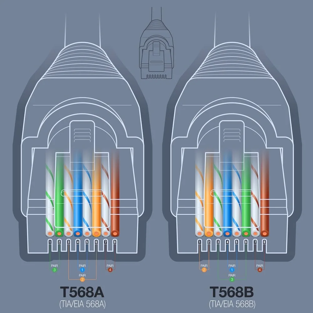
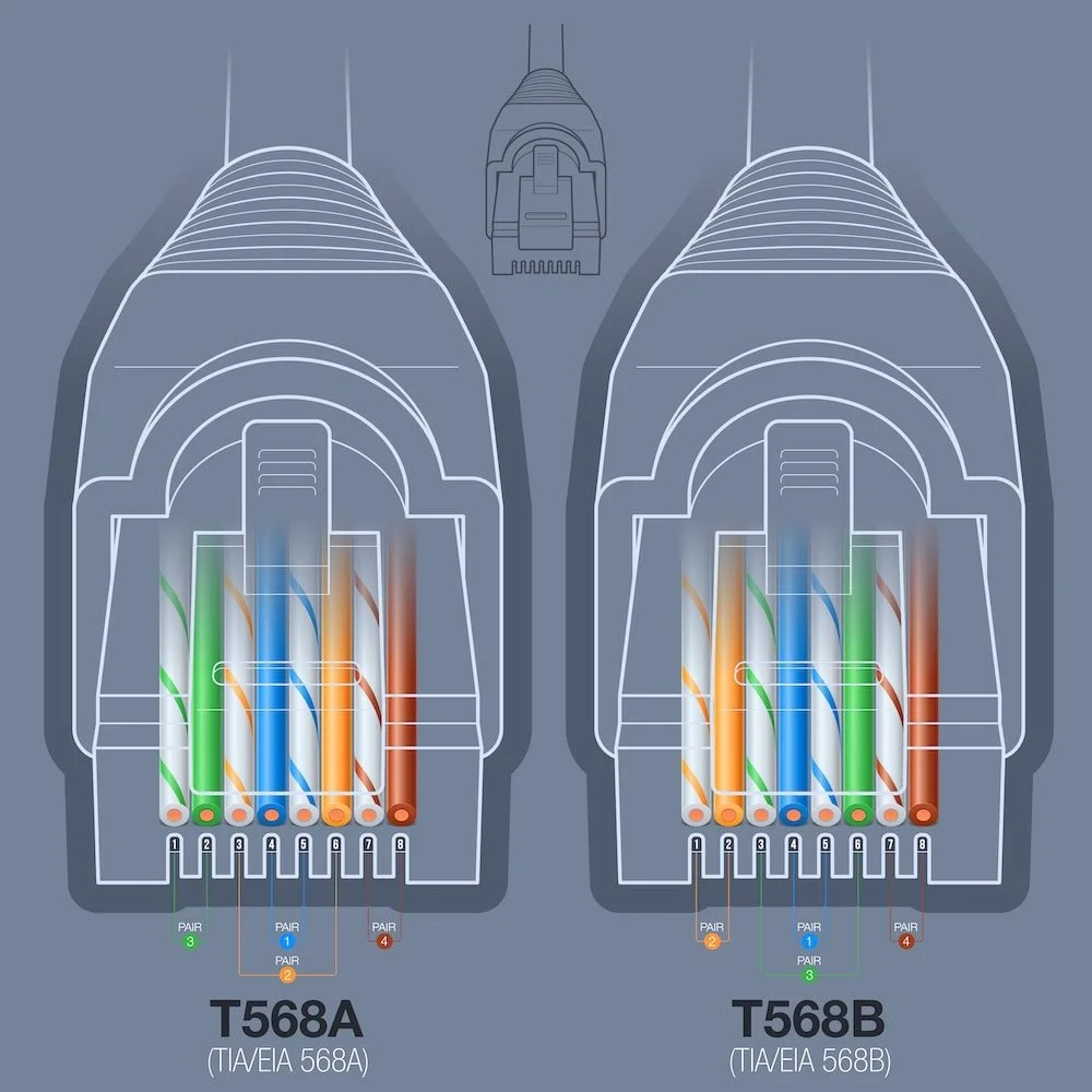
T568B: White/Orange → Orange → White/Green → Blue → White/Blue → Green → White/Brown → Brown
T568A: White/Green → Green → White/Orange → Blue → White/Blue → Orange → White/Brown → Brown
Both schemes deliver the same performance. Use the same standard on both ends of your cable. Jump to the interactive wire configurator to visualize both standards side by side.
Affiliate Disclosure: This article contains affiliate links. If you make a purchase through these links, we may earn a small commission at no extra cost to you. As an Amazon Associate, iFeelTech earns from qualifying purchases.
Last technically verified: July 23, 2026. Standards checked: ANSI/TIA-568.2-E (2024), IEEE 802.3bt.
What Is an RJ45 Connector?
An RJ45 Ethernet plug is an eight-position modular connector commonly described as 8P8C. Each pin is assigned to a specific wire color by the T568A or T568B standard. The connector itself is standardized; the wiring order is what varies.
Inside the cable, conductors are arranged in four twisted pairs. Twisting helps reject external noise and limits crosstalk between adjacent pairs, which is what makes reliable gigabit transmission possible over ordinary copper.
Why Does Ethernet Wire Order Matter?
Incorrect pair-to-pin assignments can create miswires or split pairs. Depending on the fault, a Gigabit link may negotiate at 100 Mbps or fail to establish a link entirely.
What Is the Difference Between T568A and T568B?
T568A and T568B swap the orange and green pairs on pins 1, 2, 3, and 6. That is the only physical difference.
Both standards are defined by the current ANSI/TIA-568.2-E specification and deliver identical transmission performance. Because the connector hardware is the same, the choice of standard dictates only the color sequence inside the plug. To ensure signal integrity, use the same standard on both ends of a single cable run. Mixing them creates a crossover cable rather than a standards-compliant straight-through link.
- T568B: Widely deployed in commercial and residential installations. Matches the older AT&T 258A convention.
- T568A: TIA's recognized preferred pattern. Preserves traditional one- and two-pair USOC ordering, including blue on pins 4–5 and orange on pins 3–6. Common in government and institutional projects.
Why Is T568A Preferred by TIA?
T568A's backward compatibility comes from its traditional one- and two-pair USOC ordering — the pair assignments match the Universal Service Ordering Code system used extensively for telephone service. This allows a single RJ45 jack to support both Ethernet and legacy voice connections. T568A is required when a federal contract specifies it.
Which Wiring Standard Should You Use?
Match the existing installation or project specification, then use one scheme consistently.
- Follow the contract or customer standard.
- Match the existing installation.
- For an undocumented new installation, select one accepted scheme, record it, and use it throughout.
- Use T568A when a federal contract requires it.
| Situation | Recommended Standard | Reason |
|---|---|---|
| Existing T568B site | T568B | Consistency with installed base |
| Existing T568A site | T568A | Consistency with installed base |
| Federal contract specifying T568A | T568A | Contract requirement |
| Undocumented new installation | Either (document your choice) | Both perform identically |
Interactive Wire Configurator
Use the interactive configurator below to view, compare, or test your pinout recall:
RJ45 Wiring Configurator
Interactive T568A/T568B reference
Memory Trick for T568B
"OG-BB-GB" - Remember the pairs in order: Orange, Green, Blue, Brown. For each pair, the striped wire (white/color) comes before the solid color. Exception: Green pair is split around Blue!
Full sequence: White/Orange → Orange → White/Green → Blue → White/Blue → Green → White/Brown → Brown
RJ45 Pinout for Fast Ethernet, Gigabit, and PoE
Signal use changes by Ethernet speed and PoE type even though the eight pin assignments stay fixed.
| Pins | Pair | 10/100BASE-TX | 1000BASE-T and Faster | PoE |
|---|---|---|---|---|
| 1–2 | Pair A (orange or green, depending on T568A/B) | Data | Bidirectional data | May carry power |
| 3 and 6 | Pair B (green or orange, depending on T568A/B) | Data | Bidirectional data | May carry power |
| 4–5 | Pair C (blue) | Not used for 10/100 data | Bidirectional data | May carry power |
| 7–8 | Pair D (brown) | Not used for 10/100 data | Bidirectional data | May carry power |
At 1000BASE-T and faster, all four pairs carry data bidirectionally — there is no fixed "transmit" or "receive" pair assignment, and no pair is unused.
PoE Power Levels by Type
| IEEE Standard | PoE Type | Max PSE Output | Max PD Input | Pairs Used |
|---|---|---|---|---|
| 802.3af | Type 1 | 15.4 W | 12.95 W | 2 pairs |
| 802.3at | Type 2 (PoE+) | 30 W | 25.5 W | 2 pairs |
| 802.3bt | Type 3 (PoE++) | 60 W | 51 W | 2 or 4 pairs |
| 802.3bt | Type 4 (PoE++) | 90 W | 71.3 W | 4 pairs |
Source: Ethernet Alliance PoE overview. Voltage drop between PSE and PD is expected — always design for the PD wattage, not the PSE wattage.
Tools and Connector Selection
Use a plug, crimper, cable, and tester whose published specifications are compatible.
A crimping tool, wire strippers, and a cable tester are the three essentials for every RJ45 termination.
| Tool | Purpose | Alternative |
|---|---|---|
| Ratcheting RJ45 Crimper | Seats connector pins into conductors with consistent force | Non-ratcheting crimper (less reliable) |
| Wire Strippers | Removes outer jacket without nicking conductor insulation | Built-in blade on crimping tool |
| Cable Tester | Verifies pin mapping, detects opens and shorts | Certification tester for commercial work |
| Flush-Cut Snips | Trims conductors to even length before insertion | Side cutters |
| Punch-Down Tool | Terminates conductors into keystone jacks and patch panels | — |
| Load Bars | Holds all 8 conductors in alignment during insertion | Manual alignment |
Equipment Used in This Guide

Klein Tools VDV226-110 Ratcheting RJ45 Crimper
~$50Ratcheting crimper designed for Klein pass-through RJ45 plugs. The ratchet mechanism ensures full crimp depth on every squeeze — it won't release until the cycle is complete.
Klein Tools VDV526-200 Cable Tester
~$60Verifies all 8 pins are correctly mapped and identifies open circuits, shorts, and miswiring. Test every cable before closing access or putting the link into service.
Prices checked July 23, 2026; prices vary by seller.
Match Your Plug to Your Cable Type
Many RJ45 plugs are designed for either solid or stranded cable, with different contact designs for each. Some plugs use universal three-prong contacts that accept both types. Using the wrong plug for your conductor type is a common cause of failed terminations that pass visual inspection but fail under a tester. Check the connector packaging for solid, stranded, or universal compatibility before purchasing.
Terminate an RJ45 Plug in Five Steps
Prepare the cable, preserve pair twists, seat the jacket, crimp once, and test the finished assembly.
- Strip the Jacket: Remove the length specified by the plug manufacturer (typically one to two inches) using wire strippers. Do not nick the internal conductor insulation.
- Organize the Pairs: Separate the four twisted pairs. If the cable has a spline, trim it as directed by the plug manufacturer.
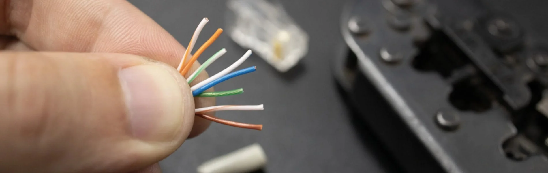
- Align to Standard: Untwist the conductors as little as possible — keep the untwisted length well under 13 mm (0.5 in.) where the connector allows. Arrange them flat according to either the T568A or T568B sequence.
- Insert and Crimp: Slide the aligned wires into the RJ45 plug until the copper tips touch the front wall. Place the plug into a ratcheting crimper and squeeze until the tool releases.
- Test: Plug both ends into a cable tester and verify all 8 pins map correctly with no shorts or opens.
Editorial Note: For reliable enterprise deployments, we recommend using a ratcheting crimper. We use the Klein Tools RJ45 Crimper in the field because its forced-release mechanism prevents the under-crimping issues common with cheaper manual tools.
Termination Details
Untwisting is the single most common cause of crosstalk failures. Keep the untwisted length as short as possible — the 13mm maximum in the TIA spec is a ceiling, not a target.
Before crimping, verify: all 8 wire tips are visible through the front of the connector, each wire is in its own channel, and the outer jacket is seated inside the connector body where the strain relief can grip it.
After crimping, tug the cable gently to confirm the jacket is gripped by the strain relief. A load bar (wire manager) holds all eight conductors in position during insertion and reduces alignment errors on standard (solid-end) connectors.
Pass-Through and Standard Plugs Compared
Pass-through plugs simplify alignment, while standard plugs fully enclose the conductor ends.
Pass-Through Connectors
Because the conductors feed entirely through the plug body, you can visually verify the color sequence before crimping. A specialized crimping tool cuts the excess wire flush during the crimp cycle. A worn or mismatched cutting blade can leave conductors protruding beyond the plug face — use a matched plug-and-tool system and inspect the finished cut.
Standard (Solid-End) Connectors
Standard connectors enclose the wire ends entirely within the plastic housing. Installers must trim the conductors to exact lengths prior to insertion. Some project specifications or cabling-system manufacturers prefer standard connectors for permanent links.
Which to Choose
Pass-through plugs simplify alignment and make the color order easy to inspect before crimping. A matched crimper must trim every conductor flush so no copper projects beyond the plug face. Standard plugs fully enclose the wire ends and may be preferred by a project specification or installer. Neither style is automatically suitable or unsuitable for PoE — suitability depends on the complete plug, cable, tool, installation, and product rating. Klein explicitly rates its Cat6 pass-through plug for PoE/PoE+.
Terminate a Keystone Jack or Patch Panel
Follow the component's A or B legend and preserve each pair's twist to the IDC termination point.
Permanent horizontal cable in a structured cabling system is normally terminated on keystone jacks (at wall outlets) and punch-down patch panels (in the telecommunications room). A male modular plug belongs on a patch cord or on a deliberately designed and tested MPTL — not on every horizontal run.
Keystone jack procedure:
- Strip the outer jacket per the jack manufacturer's instructions.
- Route each conductor into the matching color-coded IDC slot — follow the A or B legend printed on the jack, matching the site's convention.
- Keep each pair twisted as close to its IDC as possible.
- Seat and trim each conductor with a punch-down tool or the jack's integrated cap.
- Snap the completed jack into the wall plate or patch panel housing, then test.
For a more detailed walkthrough of Cat6A-specific jack and panel termination, see the Cat6A wiring diagram guide.
AWG Compatibility: Matching Your Connector to Your Cable
RJ45 connectors must be matched to the wire gauge (AWG) of your cable. Using the wrong connector is one of the most common causes of failed crimps — the wires simply won't seat into the pins.
Why AWG Matters
The channels inside an RJ45 connector are sized for a specific conductor diameter. If the wire is too thick, it won't fully insert. If it's too thin, the pin won't make reliable contact.
| Cable Category | Common AWG (Solid Horizontal) | Connector Guidance |
|---|---|---|
| Cat5e | 24 AWG | Match connector to conductor gauge |
| Cat6 | 23–24 AWG | Verify connector spec — many Cat6 cables are 23 AWG |
| Cat6A | 23 AWG (most common; 24 and 26 AWG products also exist) | Match conductor diameter, insulation diameter, cable OD, and construction to the plug specification |
Key rule: Always check the connector packaging for AWG compatibility before purchasing. Match the plug to the cable's conductor diameter, insulation diameter, jacket diameter, and construction — not to the category name alone.
Solid vs Stranded AWG
AWG ratings differ between solid and stranded cable. A 24 AWG solid conductor is slightly smaller in diameter than a 24 AWG stranded conductor (which bundles multiple thin wires). Some connectors are rated for one type only — check the label for "solid," "stranded," or "universal."
Straight-Through and Crossover Cables
Straight-through cables use one scheme at both ends; crossover cables swap pairs between ends.
Straight-Through Cables
Straight-through cables use the same wiring standard (T568A or T568B) on both ends and connect different network devices — computers to switches, switches to routers, or switches to access points. This is the standard cable type for modern networks with Auto MDI-X.
Crossover Cables
Crossover cables swap the transmit and receive pairs by wiring T568A on one end and T568B on the other. They were historically required for direct device-to-device connections (computer-to-computer, switch-to-switch) and may still be needed for legacy or industrial equipment without Auto MDI-X.
Crossover Cables Are Rarely Needed
Auto MDI-X, which automatically detects and corrects the transmit/receive pair orientation, is implemented in virtually all Gigabit Ethernet (1000BASE-T) hardware manufactured since the mid-2000s. For modern equipment, straight-through cables are all you need. However, some legacy devices, industrial equipment, and manually configured ports may still require crossover cables — keep one on hand for troubleshooting.
Test and Troubleshoot the Cable
Wire-map testing finds wiring faults, while qualification and certification measure performance. Visual inspection alone will not catch split pairs, marginal crimps, or pin-to-pin shorts.
Verification, Qualification, and Certification
| Test Level | What It Answers | Typical Tool | Approximate Cost |
|---|---|---|---|
| Verification | Are the pins mapped correctly, with no open, short, miswire, or split pair? | Klein LAN Scout Jr. (VDV526-200) | ~$60 |
| Qualification | Can this link support a stated Ethernet application (e.g., 10GbE)? | Fluke LinkIQ | ~$2,500–$3,000 |
| Certification | Does the installed link meet the full TIA or ISO category test limits? | Fluke DSX series | Five figures new; rental is common |
A passing wire map does not prove Cat6 or Cat6A performance. Never "fix" a NEXT failure by changing the standard pair assignments — reterminate with the correct pinout and minimal untwist, then retest.
Basic Continuity Testing
A basic cable tester checks that all 8 pins are wired correctly end-to-end and that no shorts or open circuits exist. Test before closing access or putting the link into service.
Testing Process:
- Connect cable ends to tester ports
- Verify that all pins show proper connectivity
- Check for correct wire mapping
- Confirm that there are no open circuits or shorts
Advanced Cable Analysis
For structured cabling in commercial environments, basic continuity testing is not sufficient. A qualification or certification tester measures the electrical characteristics that determine whether a cable will reliably support its rated speed:
Near-End Crosstalk (NEXT) NEXT occurs when a strong signal on one pair is picked up by an adjacent pair. It varies significantly with frequency — Cat5e is specified through 100 MHz, Cat6 through 250 MHz, and Cat6A through 500 MHz.
Split Pair Detection A split pair is a wire map error where one leg of a pair is terminated on the pin of a different pair. While conductors line up one-to-one on each end, they are not properly paired, causing significant crosstalk.
When to Reterminate
If testing identifies a termination fault, cut off the old plug and install a new one. Reterminate only the affected end when the tester identifies its location. Minimize the untwisted length and retest before replacing the cable run.
Fluke Networks LinkIQ Cable+Network Tester
~$2,500–$3,000Bridges the gap between a basic wire map tester and full certification. Qualifies cable bandwidth from 10BASE-T to 10GBASE-T and validates PoE delivery — the right tool when you need more than continuity but don't need a five-figure certifier.
Common Problems and Solutions
Most RJ45 termination failures fall into three categories: split pairs, crosstalk from excessive untwisting, and physical crimp defects. Each has a distinct signature on a cable tester.
Split Pair Issues
A split pair occurs when one conductor from a pair is terminated on the pin belonging to a different pair. A continuity-only tester may show pins 1–8 connected, but a split-pair-capable wire mapper will identify the pairing fault. The pairs are no longer twisted together, causing high crosstalk that degrades performance.
Identification Methods:
- Advanced cable testers with DSP capabilities
- Time domain reflectometry (TDR) testing
- Crosstalk measurement analysis
Resolution:
- Re-terminate both cable ends using correct pair assignments
- Verify proper T568A or T568B compliance
- Replace the cable if internal pair damage exists
Crosstalk Problems
Excessive crosstalk at the termination point is almost always caused by untwisting the pairs too far before inserting them into the connector.
Common Causes:
- Excessive wire untwisting during termination
- Poor quality connectors or jacks
- Incorrect pair assignments
- Physical damage to cable pairs
Solutions:
- Reterminate with the correct T568A or T568B pinout and minimal untwist, then retest
- Minimize untwisted length during termination
- Use higher-quality connectors and jacks rated for the cable category
- Replace damaged cable segments
Physical Connection Issues
Broken locking tabs are the most common physical failure. The plastic clip that locks the connector into a port is fragile — once broken, the connector will seat loosely and cause intermittent drops. Boot protectors help prevent this on cables that get moved frequently.
Incomplete crimps happen when wires are not fully seated before crimping, or when a worn tool doesn't apply enough force. If a cable fails immediately after termination, inspect the connector under good light — then cut it off and reterminate with a new plug if needed.
PoE and Shielded Cabling
PoE performance depends on pair integrity, conductor resistance, temperature, and connector quality. In a business environment, cable quality directly affects PoE reliability, switch negotiation speed, and long-term maintenance costs.
High-Power PoE and Modern Access Points
Some high-end Wi-Fi 6E and Wi-Fi 7 access points draw more power than earlier models. PoE++ (802.3bt) Type 4 supplies up to 90 W at the power-sourcing equipment (PSE) and up to about 71 W at the powered device (PD). Power travels over all four pairs simultaneously, so resistance unbalance, poor contacts, and conductor size all matter. A marginal termination that works fine for data may cause thermal issues under sustained PoE load.
Why High-Power PoE Changes Your Cabling Choice
IEEE 802.3bt Type 4 uses all four pairs and generates heat proportional to current and resistance. As cable temperature rises, insertion loss increases — and if enough cables are bundled tightly, the aggregate heat can push individual runs out of spec. ANSI/TIA-568.2-E addresses this in Annex H, which provides derating guidelines, bundle-size limits, and temperature-adjusted performance criteria for powered cabling.
The practical takeaway: Cat6 can handle high-power PoE on isolated runs, but in dense deployments (racks with many PoE++ ports feeding bundled cables), Cat6A's typical 23 AWG conductors provide useful thermal headroom. The thicker conductor dissipates heat more efficiently and maintains insertion loss margins under thermal load.
Well-terminated Cat6A cables support:
- PoE++ power delivery across all four pairs
- Multi-gig backhaul (2.5G / 5G) to Wi-Fi 6E and Wi-Fi 7 access points
- Thermal headroom for dense cable bundles under sustained high-power PoE
Patch Cable Quality
Use factory-tested patch cords at equipment connections. Terminate permanent horizontal cable on category-rated jacks and patch panels unless the project uses a standards-compliant MPTL. For UniFi deployments specifically, UniFi Premium Patch Cables are a reliable option for patch connections.
Professional Installation Standards
Business-grade cabling follows ANSI/TIA-568.2-E, which defines performance requirements by cable category, maximum run length (100 m channel), and termination practices. Adhering to the standard supports warranty claims and provides a defensible baseline. For a planning checklist covering cable selection, installation rules, and PoE budgeting, see the network cabling checklist.
Minimum documentation for a commercial installation:
- Cable labels with a consistent naming scheme
- Test results (wire map, length, NEXT, insertion loss) for every run
- As-built diagram showing cable paths and termination points
- Bend radius and separation from power cables maintained throughout
Advanced Troubleshooting
Intermittent links often require performance testing beyond a wire map.
Systematic Fault Location
Time-domain reflectometry (TDR) sends a signal pulse down the cable and measures the reflection to locate faults by distance. Most mid-range and professional testers include this feature.
Diagnostic Sequence:
- Visual Inspection: Check for apparent physical damage
- Basic Testing: Verify continuity and wire mapping
- Performance Testing: Measure crosstalk, attenuation, and delay
- Localization: Use TDR to pinpoint fault locations
Performance Optimization
Cable management has a measurable impact on performance. Ethernet cable has a minimum bend radius — typically 4x the cable diameter. Tight bends around corners compress the pairs and increase crosstalk. Use cable management rings or J-hooks rather than staples, which can deform the jacket.
Separation from power cables matters at higher frequencies. Required separation depends on circuit type, pathway, barriers, voltage, and the applicable TIA/NEC requirements — there is no single universal distance. Cross power and data cables at 90-degree angles when runs must intersect. For Cat6A in high-EMI environments, shielded (F/UTP or S/FTP) cable provides additional protection.
Shielded Cable Bonding
If you deploy shielded Cat6A (F/UTP or S/FTP), every termination point must maintain shield continuity.
Unbonded Shields Reduce Performance
Shielded cable requires shielded RJ45 connectors. The cable's drain wire (or foil contact) must make electrical contact with the metal body of the connector. An unbonded or poorly terminated shield can reduce shield effectiveness and alien-crosstalk performance. Follow the connector and cabling manufacturer's bonding instructions.
Bonding procedure: Follow the specific connector manufacturer's instructions for drain-wire routing and shield contact. Methods vary by connector design — some use a folded drain wire with conductive tape, others have an external ground tab or internal shield clamp. Do not prescribe a single universal procedure.
At the patch panel end, bond the shielded panel to the secondary bonding busbar (SBB, formerly called the TGB) per the applicable ANSI/TIA-607 design. In a structured system, the shielded patch panel is normally bonded to the SBB; the work-area jack is not separately grounded. Follow the cabling-system manufacturer's bonding instructions rather than improvising grounding topology. Leviton bonding guidance
If intermittent network issues persist after re-termination and testing, the problem may be in the structured cabling infrastructure itself. A professional cabling audit can locate marginal crimps, split pairs, and thermal derating issues that basic testers miss.
Ethernet Cable Categories and Distance Limits
Cat5e supports Gigabit, Cat6 adds limited-reach 10 Gigabit, and Cat6A supports 10 Gigabit to 100 m.
Cable Category Selection
| Category | Reliable Baseline | Higher-Speed Guidance | Editorial Recommendation |
|---|---|---|---|
| Cat5e | 1 Gb/s to 100 m | Installed channels may support 2.5/5 Gb/s to 100 m when qualified | Still specified by TIA-568.2-E; suitable for existing Gigabit installations |
| Cat6 | 1 Gb/s to 100 m | 10 Gb/s to 37 m; 37–55 m depends on alien-crosstalk environment | Reasonable choice for many new residential runs |
| Cat6A | 10 Gb/s to 100 m | Preferred for full-distance 10G, dense PoE, and high-bandwidth AP links | Stronger choice when full-distance 10G or dense PoE justifies the cost |
Cat5e is still specified by ANSI/TIA-568.2-E and is not deleted from the standard. Installed Cat5e and Cat6 channels can support 2.5/5GBASE-T to 100 m when the channel qualifies (Fluke Networks). Cat6A is the strongest choice for 10GbE AP backhaul, dense PoE bundles, and long service life. For a deeper comparison, see our best ethernet cable guide. For Cat6A-specific termination, see the Cat6A wiring diagram guide.
Planning Considerations
- Multi-gig ports (2.5G / 5G) are common on business-class Wi-Fi 6E and Wi-Fi 7 access points. These speeds can run over Cat5e and Cat6 to 100 m when the channel qualifies — Cat6A is not required for multi-gig.
- PoE++ (802.3bt) uses all four pairs for high-power delivery. Conductor size, resistance, temperature, and bundle density all matter. See the thermal loading section and the PoE power table for details.
- Shielded cabling is increasingly deployed in high-EMI environments. If you install F/UTP or S/FTP, budget for shielded connectors, shielded patch panels, and proper bonding infrastructure from the start.
When Should You Hire a Cabling Contractor?
Hire a contractor when code, warranty, grounding, uptime, or certified test reports matter. DIY termination is practical for patch cables, small home runs, and lab environments.
DIY is appropriate when:
- Making patch cables for a home lab or desk setup
- Adding a single run in a residential setting
- Learning termination technique on non-critical cable
Hire a certified cabling contractor when:
- Installing infrastructure for a business with uptime requirements — see our business network wiring installation guide for cost expectations and code requirements
- The installation requires a manufacturer's warranty (which requires certified testing documentation)
- The environment has EMI challenges (near HVAC, motors, or fluorescent lighting)
- Local code, warranty, or compliance requires documented test results (TIA-1152-A specifies field-test-instrument accuracy and reporting, but is not itself a building code)
Documentation and Warranty
Test results prove the cable was good at installation time — which matters when troubleshooting a problem months later.
What to Document
- Wire map for every terminated cable
- Cable length for each run (required for warranty claims)
- Performance parameters: NEXT, insertion loss, and delay skew
- Pass/fail result against the applicable TIA category standard
- Cable labels matching a consistent naming scheme tied to your network diagram
Manufacturer Warranty Requirements
Most structured cabling warranties (Belden, Panduit, CommScope) require:
- All components from the same certified channel solution (cable, connectors, patch panels from the same manufacturer's program)
- Installation by a certified technician
- Test results submitted to the manufacturer within a specified window
Without these, you have a functional cable — but no warranty if it fails prematurely.
RJ45 Termination Checklist
Match the scheme, preserve pair twists, use compatible components, and test every finished link.
Quick Checklist
- Standard: Use T568A or T568B — match the site, document the choice, and use it consistently
- AWG: Match your connector to your cable's conductor diameter, insulation diameter, and construction
- Connector type: Pass-through for alignment ease; standard for enclosed conductors — both can support PoE when properly rated
- Untwist length: Keep pairs twisted as close to the termination point as the connector allows
- Testing: Test every cable with a wire mapper at minimum; qualify or certify as the project requires
- Documentation: Record wire map, length, and pass/fail for each run
RJ45 termination is a learnable skill with a short feedback loop — a cable tester tells you immediately whether the crimp worked. The most common mistakes are untwisting pairs too far, mismatching the connector to the cable, and skipping the test. Get those three things right and the rest follows.
If you're wiring a single desk or a home lab, the guide above has everything you need. For a business installation with uptime requirements, the investment in proper tools, compatible components, and documented test results pays for itself the first time you need to troubleshoot a problem or make a warranty claim.
Frequently Asked Questions
These answers cover speed, length, connector reuse, split pairs, and cable construction.
Does T568A or T568B matter for network speed?
No. Both wiring schemes deliver identical transmission performance. The only physical difference is the swap of the orange and green pairs on pins 1, 2, 3, and 6. The critical requirement is using the same standard on both ends of the cable.
What's the maximum length for Ethernet cables?
The maximum channel length for Cat5e, Cat6, and Cat6A is 100 meters (328 feet). This includes the permanent link plus patch cords at each end. Beyond this, signal attenuation increases and the link may fail to negotiate at its rated speed.
Can I reuse RJ45 connectors after termination?
No. Once crimped, the metal pins are permanently deformed into the conductors and the strain relief is set. A re-crimped connector will not make reliable contact. Cut the connector off and use a new one.
How do I identify split pair problems?
Split pairs are best detected using specialized digital cable testers to identify splits and measure distance to faults. Basic multimeters won't detect split pairs if the circuit is complete.
Why is my network speed capped at 100 Mbps instead of Gigabit?
Gigabit Ethernet (1000BASE-T) requires all four pairs — all 8 pins — to be correctly terminated. Fast Ethernet (100BASE-TX) only uses two pairs, so a cable with wiring errors on pins 4, 5, 7, or 8 will still pass a basic link test at 100 Mbps. Re-terminate both ends and verify all 8 pins with a cable tester.
What's the difference between solid and stranded Ethernet cable?
Solid core cables have single copper wires per conductor — ideal for permanent installations and long runs through walls. Stranded cables have multiple thin copper strands per conductor — better for patch cables that get flexed frequently. Use solid cable for structured cabling and stranded for patch cords. Some RJ45 connectors are designed specifically for solid or stranded cable, while universal-contact designs accept both.
Can I use Cat6 connectors on Cat5e cable?
Physical fit is possible because the 8P8C connector form factor is the same, but compatibility is not guaranteed. Check conductor and jacket dimensions against the connector specification. A Cat6 connector designed for 23 AWG may not make reliable contact on a thinner 24 AWG Cat5e conductor. Do not claim category performance without testing.
Do I need all 8 wires for Gigabit speeds?
Yes. Unlike 10/100 Mbps Ethernet which only uses 4 wires (pins 1,2,3,6), Gigabit Ethernet uses all 8 wires. If a conductor fails, the link may negotiate at 100 Mbps or fail entirely. Always terminate and test all 8 conductors.
Primary Sources
- ANSI/TIA-568.2-E publication announcement — current balanced twisted-pair cabling standard (2024)
- Ethernet Alliance PoE overview (PDF) — IEEE 802.3bt Type 1–4 power specifications
- Fluke Networks: T568A vs T568B — wiring-scheme comparison
- Fluke Networks: termination guidance — pair-twist preservation at the connector
- Fluke Networks: 10GBASE-T field testing — Cat6 distance limits and alien crosstalk
- Fluke Networks: 2.5/5GBASE-T cable plant support — multi-gig over Cat5e and Cat6
- Klein Tools: Cat6 pass-through plug specification — PoE/PoE+ compliance
- Leviton: patch-panel bonding application note (PDF) — TIA-607 bonding design
- Siemon: ANSI/TIA-568.2-E summary — including Annex H powered-cabling and bundling guidance
Quick Reference Card
RJ45 Quick Reference
Print this page for workbench reference
- Use the same standard on both ends — match the site convention
- Minimize untwist: keep pairs twisted as close to the termination as possible
- All 8 wires required for Gigabit speeds and above
Related Articles
More from Network Infrastructure
Cat6A Wiring Diagram Guide: T568A/B Pinouts, Termination & Testing
Wire Cat6A with T568A and T568B pinouts, connector-selection guidance, MPTL steps, PoE facts and Cat6A testing requirements.
19 min read
Best Ethernet Cables 2026: Cat6, Cat6A, and When You Need Shielded
We've pulled Cat6A, shielded, outdoor, and direct-burial cables across 50+ business installs. What we recommend — by use case and environment.
29 min read

How Many UniFi Access Points, Switch Ports, and Cameras Do You Need? Our Sizing Rules
Sizing rules from 200+ UniFi installs: access points per square foot, switch port math, camera density, and NVR thresholds — plus a free configurator.
14 min read