

Cat6A Wiring Diagram Guide: T568A/B Pinouts, Termination & Testing
Wire Cat6A with T568A and T568B pinouts, connector-selection guidance, MPTL steps, PoE facts and Cat6A testing requirements.

Key Takeaway
Cat6A uses the same T568A and T568B pinouts as Cat5e and Cat6. Its main advantage is standards-compliant 10GBASE-T over a channel up to 100 meters (ANSI/TIA-568.2-E). Wi-Fi 7 does not itself require Cat6A, 10GbE, or PoE++—check the access point's Ethernet port, PoE class, link length, and project specification before selecting cable. IEEE 802.3bt Type 4 can supply up to 90 W at the PSE, with up to 71.3 W available at the powered device (Ethernet Alliance).
Category 6A (Cat6A) cabling supports 10GBASE-T over a full 100-meter channel at frequencies up to 500 MHz. It is a strong default for new installations that require multi-gigabit speeds, dense cable bundles, or high-power PoE—but cable category should always be matched to the device's actual port speed, power class, and link length rather than chosen by Wi-Fi generation alone.
This guide covers current wiring standards (ANSI/TIA-568.2-E, published in 2024), termination techniques, connector selection, and testing requirements. For comprehensive cable selection guidance, see our Ethernet cable selection guide.
Last technically verified: July 23, 2026.
Affiliate Disclosure: This article contains affiliate links. If you make a purchase through these links, we may earn a small commission at no extra cost to you. As an Amazon Associate, iFeelTech earns from qualifying purchases.
What Is Cat6A Cable?
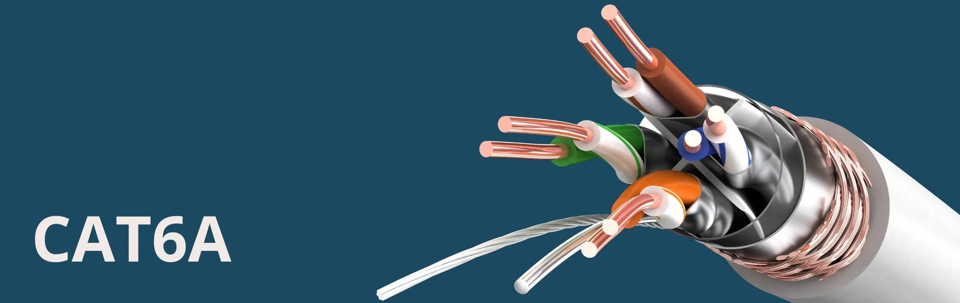
Cat6A is 500 MHz balanced copper cabling designed for 10GBASE-T channels up to 100 meters.
Cat6A Cable Specifications
Cat6A cables are defined by transmission performance—not by a single physical construction. For a detailed comparison of cable categories, see our Cat6 vs Cat6A comparison guide.
Conductor Design:
- Most permanent-link cables use 23 AWG solid copper conductors, though other gauges exist (e.g., 26 AWG stranded for patch cords)
- Tighter twist ratios to reduce crosstalk
- Improved jacket materials for durability
Shielding Constructions:
- U/UTP: Unshielded—no foil or braid
- F/UTP: Overall foil shield around all four pairs
- U/FTP: Individual foil shield around each pair, no overall shield
- F/FTP: Individual pair foils plus an overall foil
- S/FTP: Individual pair foils plus an overall braid
Performance Requirements (ANSI/TIA-568.2-E):
- Supports 10GBASE-T to 100 meters (complete channel: up to 90 m permanent link plus patch cords)
- Operating frequency up to 500 MHz (vs 250 MHz for Cat6)
- Normative alien crosstalk (AXT) specifications
- Enhanced return loss performance
Physical Characteristics:
- Cable diameter varies by construction and fire rating (commonly 6.5–8.5 mm for permanent cables)
- Increased pair separation to minimize crosstalk
- Connector, tool, and cable must be matched by gauge, insulation diameter, jacket diameter, and shield type
Cat6A Wiring Diagrams: T568A and T568B Pinouts
Cat6A uses the same eight-pin T568A and T568B color order as other four-pair category cable.
Interactive Wire Configurator
Use this interactive tool to visualize the exact wire order for T568A and T568B standards. Switch between View, Compare, and Test modes to practice:
RJ45 Wiring Configurator
Interactive T568A/T568B reference
T568B Wire Order
White/Orange → Orange → White/Green → Blue → White/Blue → Green → White/Brown → Brown
For each pair, the striped conductor (white/color) comes first. The green pair is split around the blue pair at pins 3 and 6.
Pin Assignments
| Pin | T568A | T568B |
|---|---|---|
| 1 | White/Green | White/Orange |
| 2 | Green | Orange |
| 3 | White/Orange | White/Green |
| 4 | Blue | Blue |
| 5 | White/Blue | White/Blue |
| 6 | Orange | Green |
| 7 | White/Brown | White/Brown |
| 8 | Brown | Brown |
The diagram shows the plug with the gold contacts facing you, the latch facing away, and pin 1 on the left. Verify this orientation matches any printed reference or connector label before terminating—a mirrored plug image is one of the easiest ways to create a bad termination.
Pair Numbering and Data Roles
The blue pair is Pair 1 (pins 4–5), orange is Pair 2, green is Pair 3, and brown is Pair 4. T568A and T568B change only the positions of the orange and green pairs.
Data and Power Usage by Speed
- 10/100BASE-TX: Uses two pairs for data (pins 1–2 and 3–6). The blue and brown pairs carry no data at these speeds but may carry PoE power.
- 1000BASE-T and faster (2.5G, 5G, 10GBASE-T): All four pairs carry data bidirectionally. There is no fixed "transmit" or "receive" pair assignment.
- PoE (IEEE 802.3af/at, Types 1 and 2): Power is delivered over two pairs—either pins 1–2 and 3–6 (Mode A) or pins 4–5 and 7–8 (Mode B).
- PoE++ (IEEE 802.3bt Type 3): Up to 60 W at the PSE; up to 51 W available at the powered device. May use two or four pairs.
- PoE++ (IEEE 802.3bt Type 4): Up to 90 W at the PSE; up to 71.3 W available at the powered device. Always uses all four pairs. Ethernet Alliance
PoE power coexists with data on the same pairs—they are not "unused" or "PoE-only" at gigabit speeds and above.
Choose One Wiring Scheme for Each Link
Straight-through links use the same wiring scheme at both ends and are the normal structured-cabling configuration.
Use T568A or T568B at both ends of each link; match the site's existing scheme. Different links in one building may use different schemes without creating a crossover—a crossover occurs only when opposite ends of the same link use different schemes.
| Standard | Usage | Notes |
|---|---|---|
| T568B | Widely deployed in commercial and residential installations | — |
| T568A | TIA's recognized preferred pattern; backward-compatible with two-pair USOC wiring | Common in government and institutional projects |
Both Standards Perform Identically
There is no performance difference between T568A and T568B—both provide equivalent transmission characteristics (Fluke Networks). Use the project specification, match the existing installation, or document one site convention for new work.
Straight-through Cat6A cables connect:
- Computers to switches
- Access points to switches
- Switches to routers
- Any device in structured cabling systems
Crossover cables (T568A on one end, T568B on the other) are unnecessary for most current equipment due to Auto-MDI/MDIX, which has been standard in Gigabit Ethernet ports for over 20 years. Legacy and specialist cases may still require crossovers.
Tools and Components for Cat6A Termination
Match every plug, jack, and tool to the cable's gauge, insulation diameter, jacket diameter, and shield type.
Professional Termination Tools
Essential Tools (select by termination method):
- Cat6A crimping tool — for crimp plugs; use only with connector-approved cable types
- Cat6A field termination plugs — for MPTL and direct-connect installations
- Punch-down tool — for keystone jacks
- Cable stripper with adjustable depth
- Wire cutter with clean cutting edges
- Cable tester — see Testing section for verification vs. qualification vs. certification
Recommended Components:
- Cat6A field termination plugs — approximately $2–10 each depending on type (feed-through crimp plugs vs. tool-free field plugs)
- Cat6A-rated RJ45 connectors (match to cable conductor type and gauge)
- Cat6A bulk cable (verify fire rating: CMR, CMP, CMX as required)
- Cable boots and strain relief
- Label maker for proper documentation
Recommended Field Plug Products:
- Platinum Tools ezEX48 (Cat6A, 23–22 AWG, solid or stranded) — feed-through crimp plug requiring compatible crimper (Platinum Tools)
- IDEAL 85-368 (shielded feed-through crimp plug for Cat6A/6/5e) — requires IDEAL FT-45 crimp tool; supports conductors 0.040–0.048 in. diameter, max jacket 0.320 in. (IDEAL product page)
Connector Compatibility
Physical fit does not prove Cat6A component performance. Match the connector to the cable's category rating, conductor type (solid or stranded), AWG, insulation diameter, jacket diameter, shield type, and use the manufacturer's approved tool. Standard Cat5e or Cat6 connectors should not be used for Cat6A-rated links.
How To: Terminate a Shielded Cat6/6A RJ45 Connector
Choose Jacks, Crimp Plugs, or Field Plugs by Link Type
Use jacks for permanent links, factory cords for patching, and a rated field plug for an MPTL.
When to Use Each Method
| Method | Best For | Key Consideration |
|---|---|---|
| Keystone Jacks | Permanent horizontal links—patch panels and work-area outlets | Standard termination for structured cabling |
| Factory Patch Cords | Movable equipment connections and rack patching | Pre-tested stranded construction |
| Field Termination Plugs | MPTL connections to fixed APs, cameras, sensors, or displays | Eliminates the outlet; use the correct adapter for MPTL certification |
| Crimp Plugs | Only when the plug maker explicitly approves the cable's conductor type, gauge, and diameter | Requires matching crimper; verify solid-cable compatibility |
Choosing the Right Termination
- Terminate ordinary horizontal cable in Cat6A jacks at the patch panel and work-area outlet.
- Use factory-terminated stranded patch cords for movable equipment and rack patching.
- Use an MPTL (Modular Plug Terminated Link) when a fixed AP, camera, sensor, or display should connect directly to the horizontal cable without an outlet.
- Use a crimp plug on solid cable only when the plug maker explicitly approves the cable's conductor type, gauge, insulation diameter, jacket diameter, and shield construction.
Advantages of Field Termination Plugs for MPTL
- Designed for the conductor diameters typical of permanent Cat6A cable
- Designed to preserve pair geometry for Cat6A performance
- Many models allow retermination if needed
- Tool-less designs can reduce termination time
Advantages of Keystone Jacks
- Standard approach for permanent horizontal links per TIA topology
- Wide selection of component-rated products
- Tested and warrantied as part of structured cabling systems
- Punch-down termination is well-established
Crimp Plugs and Solid Cable
Cat6A crimp plugs rated for solid cable do exist—the connector specification determines compatibility, not a universal rule against crimping solid conductors. However, using a crimp plug not rated for the cable's exact gauge and insulation diameter risks connection failure. Always verify the connector datasheet.
Terminate Cat6A Cable Step by Step
Follow the connector maker's strip lengths and preserve pair twists to the point of termination.
General Termination Procedure
- Confirm compatibility — Verify the cable and connector are rated for the same category, conductor type, AWG, insulation diameter, jacket diameter, and shield construction.
- Cut the cable square — Inspect the jacket end for damage.
- Strip only the length specified by the connector maker — A single generic strip length cannot safely cover crimp plugs, field plugs, jacks, shielded cable, and unshielded cable. Follow the product instructions.
- Prepare the separator, foil, braid, and drain wire exactly as instructed — For shielded cable, handle shield components per the connector's documented procedure.
- Keep each pair twisted until it reaches the wire manager or IDC — Preserve twist as close to the termination point as possible.
- Arrange conductors in T568A or T568B order — Verify the color sequence before proceeding.
- Seat the jacket under the connector's strain-relief mechanism — This provides mechanical support and prevents conductor pull-out.
- Close, crimp, or punch down using the specified tool — Use the correct tool and pressure setting for the connector.
- Inspect — Verify pin order, conductor seating, shield contact (if shielded), and strain relief.
- Test — Use the method appropriate to the job (verification, qualification, or certification).
No Universal Strip Length
Different connector types require different preparation dimensions. A field plug, crimp plug, and keystone jack each have distinct strip lengths, conductor trim lengths, and assembly sequences. Always refer to the specific connector's installation guide.
How Does Cat6A Differ from Cat6?
Cat6A doubles rated bandwidth to 500 MHz and supports 10GBASE-T over a 100-meter channel.
Cat6A vs Cat6 Key Differences
While both categories use identical T568A/T568B pin assignments, Cat6A has stricter performance requirements that affect installation:
Installation Differences:
- Minimum bend radius is commonly 4× the cable's outer diameter for installed cable, though pulling conditions and product instructions may require more
- Preserve pair twists as close to the termination point as possible; follow the connector's product-specific instructions for maximum untwist
- Shielded installations require compatible hardware and a bonding design per ANSI/TIA-607-E
- Normative alien crosstalk testing is part of the Cat6A specification
Performance Benefits:
- 10GBASE-T capability over a full 100-meter channel
- Normative alien crosstalk resistance specifications
- Higher frequency response (500 MHz vs 250 MHz)
- Useful thermal headroom for high-power PoE in dense bundles
Cat6 vs Cat6A Comparison
| Specification | Cat6 | Cat6A |
|---|---|---|
| Maximum Frequency | 250 MHz | 500 MHz |
| 10GBASE-T Distance | 37 m guaranteed; 37–55 m depends on alien-crosstalk environment | 100 meters (full channel) |
| Alien Crosstalk Spec | No normative field requirement | Normative AXT performance limits |
| Pair Twist | Preserve per connector instructions | Preserve per connector instructions |
Troubleshoot Failed Cat6A Terminations
Most failures come from split pairs, excess untwist, poor shield contact, wrong components, or excessive length.
Common Failure Causes
Wiring Order Mistakes (Split Pairs): The most common error involves swapping conductors between pairs. A wire map tester will identify crossed or split pairs. Always verify the color sequence before completing termination.
Excessive Pair Disturbance: Cat6A's higher frequency requirements make it sensitive to any deviation in pair geometry. Preserve pair twists as close to the termination point as the connector allows and follow the product's documented dimensions.
Incompatible Connectors: Using connectors not rated for the cable's category, gauge, or construction can produce a link that passes basic wiremap but fails insertion loss, NEXT, or return loss at Cat6A frequencies.
Inadequate Testing: Basic continuity testing (wire map) does not verify Cat6A performance compliance. Qualification or certification testing is needed to identify frequency-dependent issues.
Frequent Installation Issues
- Using different schemes at opposite ends of the same link (creates a crossover)
- Exceeding the cable maker's bend-radius or pulling-tension limits
- Failing to maintain pair geometry throughout termination
- Using a connector or tool not matched to the cable
- Testing only wiremap without frequency-dependent measurements
Which Standards Apply to Cat6A in July 2026?
ANSI/TIA-568.2-E is the current US balanced twisted-pair component standard.
Applicable Standards
- ANSI/TIA-568.2-E (published 2024) — Balanced twisted-pair cabling and components. Replaces 568.2-D with corrections, updated nomenclature, and DC resistance unbalance (DCRU) testing requirements. TIA announcement
- ANSI/TIA-607-E — Generic telecommunications bonding and grounding for customer premises. TIA
- IEEE 802.3bt — Type 3 and Type 4 PoE power definitions.
- The project specification, cabling-system warranty, local code, and manufacturer instructions.
These are voluntary industry standards unless incorporated into a contract, warranty, code, or other enforceable requirement. Installations specified as Cat6A should be designed and tested to the applicable standard.
Cat6A Testing Parameters:
- Wire map verification
- Length measurement
- Insertion loss across the frequency range
- Near-end crosstalk (NEXT) and power-sum NEXT (PSNEXT)
- Attenuation-to-crosstalk ratio, near-end (ACR-N) and power-sum (PSACR-N)
- Attenuation-to-crosstalk ratio, far-end (ACR-F, formerly called ELFEXT) and power-sum (PSACR-F)
- Return loss
- Propagation delay and delay skew
- Alien crosstalk (AXT) testing where required
Bond and Terminate Shielded Cat6A Correctly
Shielded channels need compatible hardware and a bonding design that follows ANSI/TIA-607-E and site rules.
Shielded Cat6A Requirements
Shielded Cat6A requires a coherent component and bonding design throughout the channel:
Bonding Design:
- All components in the channel must be shielded and category-rated (cable, connectors, patch panels, patch cords)
- Shield continuity must be maintained from end to end
- The channel's shield connects to the premises bonding infrastructure per ANSI/TIA-607-E
- 360-degree shield contact at each termination point provides the most effective shield performance
Shield Bonding
A shielded cabling system requires a designed bonding path. Correctly bonded systems do not inherently create harmful ground loops—ground-loop problems typically arise from improper or incomplete bonding, not from shielding itself. Follow the cabling system manufacturer's bonding instructions and ANSI/TIA-607-E design guidance.
An unbonded or partially bonded shield can reduce performance, which is why shielded installations require more planning than UTP. If the bonding infrastructure is unavailable or impractical, U/UTP Cat6A may be simpler and still meets all Cat6A performance requirements.
Installation Best Practices:
- Use shielded components throughout—do not mix shielded and unshielded in the same channel
- Maintain shield integrity during termination per the connector manufacturer's procedure
- Document the bonding path for maintenance
- Distinguish permanent-link shield continuity, rack bonding, and the complete channel through connected equipment
Verify Wiring, Qualify Speed, or Certify Performance
A wire mapper checks continuity; a qualifier checks application speed; a certifier proves standards compliance.
Test Levels
| Test Level | What It Establishes | Typical Use | Equipment Class |
|---|---|---|---|
| Verification | Wiremap, opens, shorts, crossed or split pairs, approximate length | Basic installation checks | Wire mapper ($20–$100) |
| Qualification | Whether the link can support an application such as 1GbE or 10GbE | Troubleshooting and small deployments | Network qualifier (e.g., Fluke LinkIQ, ~$3,000) |
| Certification | Pass/fail against a defined TIA or ISO category test limit | Commercial acceptance, warranty, documentation | Standards certifier (typically $10,000+, e.g., Fluke DSX-8000) |
Testers Are Not Interchangeable
A $30 wire mapper, a ~$3,000 qualifier (like the Fluke LinkIQ), and a five-figure certifier (like the Fluke DSX-8000) serve fundamentally different purposes. A qualifier confirms that an application can run on the link but does not certify compliance with TIA category limits. Only a standards certifier issues Cat6A certification reports. Choose the test level appropriate to the project's requirements.
Cat6A Certification Parameters
Cat6A certification includes: insertion loss, NEXT, PSNEXT, ACR-N, PSACR-N, ACR-F (formerly called ELFEXT), PSACR-F, return loss, length, propagation delay, delay skew, and applicable alien-crosstalk testing.
MPTL Testing
To certify an MPTL to TIA limits, use a permanent-link adapter at the jack end and a category-matched patch-cord adapter at the plug end. A channel adapter at the plug end can exclude the installed plug's mated performance and produce misleading results. Fluke MPTL guidance
Alien Crosstalk Testing
Cat6A has normative alien crosstalk (AXT) performance requirements. Alien-crosstalk programs use a project- or warranty-defined sample of disturbed links, typically including representative short, medium, and long links in worst-case connector and bundle positions—not every installed link. Fluke sampling guidance
When Should You Choose Cat6A?
Choose Cat6A for new 10GbE runs, dense bundles, long service life, or projects that specify high-power PoE.
Application Scenarios
Strong reasons to choose Cat6A:
- 10GBASE-T requirements: Specify Cat6A for new links that require standards-assured 10GBASE-T beyond 37 meters. Existing Cat6 links from 37–55 m may work after alien-crosstalk assessment.
- Dense cable bundles: Cat6A's normative alien-crosstalk specs protect performance in crowded pathways
- High-power PoE: Cat6A's typical 23 AWG conductors provide useful thermal headroom for Type 3/4 PoE in bundles, though lower categories can also carry high-power PoE in appropriate conditions
- Multi-gigabit switches: 2.5G, 5G, and 10G infrastructure benefits from Cat6A headroom
- Long planned service life: Projects planning a 15+ year technology lifecycle
Wi-Fi 7 and Cat6A:
Wi-Fi 7 does not itself require Cat6A. The cable category depends on the AP's Ethernet port speed, PoE class, and link length:
| Example AP | Wired Uplink | Power Requirement | Cat6A Needed? |
|---|---|---|---|
| Ubiquiti U7 Pro Wall | 2.5GbE | PoE+ (802.3at) | Not required by the AP itself (Ubiquiti) |
| Cisco Wireless 9172I | 2.5GbE | 802.3at (25.5 W PD) for full radios; 802.3bt Class 5 to enable USB | Not required by the AP itself (Cisco) |
| TP-Link EAP770 | 10GbE | 802.3bt PoE++ | Cat6A recommended—10GbE uplink needs Cat6A for standards-assured operation beyond 37 m (TP-Link) |
Cat6A is a strong default for new enterprise AP cabling because it supports 10GBASE-T over 100 meters and provides thermal headroom for PoE. It is not a Wi-Fi 7 requirement.
Recommended Applications:
- Dense installations with significant alien crosstalk potential
- PoE+ and PoE++ device deployments in bundles
- Data center horizontal cabling
- Industrial environments requiring enhanced performance
Cost Considerations:
- Material costs vary by manufacturer, fire rating, shielding, and quantity—obtain like-for-like quotes
- Installation labor may increase due to larger cable diameter and shielded-cable handling
- Long-term value through extended technology lifecycle
- Reduced probability of future cable replacement for bandwidth upgrades
Cat6A Tools and July 2026 Prices
Tool cost depends on whether you verify wiremap, qualify 10GbE, or issue Cat6A certification reports.
Essential Equipment by Installation Type
Planning estimates as of July 23, 2026. Linked items have verified sources; unlinked ranges are representative. Tax, shipping, and volume discounts excluded.
| Tool/Component | Solid-Core (Permanent) | Stranded (Patch Cables) | Approximate Cost |
|---|---|---|---|
| Cable Stripper | Adjustable-depth stripper rated for Cat6A diameter | Same | $15–30 |
| Termination Method | Field plugs, keystone jacks, or rated crimp plugs | Crimp connectors matched to stranded cable | ~$2–10 per plug; component-rated jacks $20–27+ |
| Installation Tool | Punch-down tool or plug-specific compression/crimp tool | Cat6A crimping tool | $50–150 |
| Wire Mapper | Basic wiremap/continuity tester | Same | $20–100 |
| Qualifier | Application qualifier (e.g., Fluke LinkIQ) | Same | ~$3,000 |
| Certifier | Standards certifier (e.g., Fluke DSX-8000) | Same | $10,000+ |
| Wire Cutters | Flush-cut for clean ends | Same | $10–25 |
| Bulk Cable | Solid Cat6A—verify fire rating (CMR, CMP, CMX) and shielding | Stranded Cat6A patch cord cable | ~$0.40–0.55/ft (1,000 ft; varies by fire rating and shielding) |
Price Notes
- Component-rated Cat6A jacks (e.g., Leviton Atlas-X1) are typically $20–27 each; commodity unrated jacks may cost less but may not provide documented Cat6A performance.
- Feed-through crimp plugs (e.g., IDEAL 85-368 25-pack) can cost approximately $2–3 per plug. Tool-free field plugs typically cost $7–10 each.
- A qualifier like the Fluke LinkIQ (~$3,000) confirms 10GbE application support but is not a TIA certification instrument. Cat6A certifiers are a separate, typically five-figure equipment class.
When to Hire a Professional
Professional installation recommended for:
- Large-scale deployments (50+ drops)
- Shielded Cat6A implementations requiring designed bonding
- Projects requiring Cat6A certification reports for warranty compliance
- MPTL installations requiring correct test-adapter selection
- Mission-critical network infrastructure
DIY feasible for:
- Small installations (under 10 drops) with appropriate tools and testing
- Non-critical applications where qualification (not certification) suffices
- Budget constraints with available technical skills and correct components
Before starting any cabling project, review our network cabling checklist for proper planning and preparation.
Need Professional Cat6A Installation?
Our experienced cabling technicians provide Cat6A certification reports, MPTL testing, PoE validation, labeling, and warranty documentation for commercial and residential projects.
Request a Professional AssessmentPlan Cat6A Around the Device and Switch
Confirm the device's port speed, PoE class, and connector before choosing cable or termination.
Equipment Compatibility
Cat6A cabling is backward-compatible with common BASE-T applications:
Backward Compatibility:
- Supports common BASE-T applications: 10BASE-T, 100BASE-TX, 1000BASE-T, 2.5GBASE-T, 5GBASE-T, and 10GBASE-T
- Works with existing network switches and equipment using 8P8C (RJ45) connectors
- Provides performance headroom for future speed upgrades
- Maintains standard RJ45 connector compatibility
Planning Considerations:
- Verify the device's Ethernet port speed before assuming 10GbE is needed
- Confirm the device's PoE class (Type 1/2/3/4) and actual power draw
- Match the switch's PoE budget to the devices it will power
- Consider cable pathway capacity—Cat6A's larger diameter affects conduit fill
Cat6A Wiring FAQ
These answers cover connector compatibility, T568A versus T568B, pair untwist, testing, and Wi-Fi 7.
Can I use Cat6 connectors with Cat6A cable?
Physical fit does not prove Cat6A component performance. Cat6A connectors are designed for the specific conductor gauge, insulation diameter, and jacket diameter of Cat6A cable. Using a lower-rated connector may produce a link that passes wiremap but fails Cat6A frequency-dependent tests. Always match the connector's category rating and dimensional specifications to the cable.
What's the difference between T568A and T568B wiring?
Both standards provide identical transmission performance (Fluke Networks). They differ only in the position of the orange and green pairs. T568B is widely deployed; T568A is TIA's recognized preferred pattern with backward compatibility to two-pair USOC wiring. The critical requirement is using the same standard on both ends of each link.
How much can I untwist Cat6A pairs during termination?
There is no single universal untwist dimension that applies to all Cat6A connectors. Preserve pair twists as close to the termination point as the connector allows, and follow the connector manufacturer's documented maximum. Excessive untwist degrades near-end crosstalk performance at Cat6A frequencies.
Do I need special tools for Cat6A termination?
Cat6A requires connectors and tools rated for the cable's specifications. The connector, cable, and tool must be compatible by category, conductor type, AWG, and dimensions. Using tools designed for Cat5e or Cat6 on Cat6A cable risks improper termination.
Does Wi-Fi 7 require Cat6A?
No. Wi-Fi generation does not determine cable category. The cable choice depends on the AP's Ethernet port speed, PoE class, link length, and project specification. Some Wi-Fi 7 APs use 2.5GbE and PoE+ (e.g., Ubiquiti U7 Pro Wall), while others use 10GbE and PoE++ (e.g., TP-Link EAP770). Cat6A is a strong default for new enterprise AP cabling, but it is not a universal Wi-Fi 7 requirement.
Can Cat6 cable support PoE++?
Yes. Properly designed Cat5e and Cat6 channels can carry IEEE 802.3bt power. Cat6A is generally preferable for new high-power PoE installations because of its typical conductor size and reduced bundle heating—not because lower categories categorically cannot carry it. See the Ethernet Alliance cabling guidance for details.
What testing is required for Cat6A installations?
The required test level depends on the project: verification (wiremap), qualification (application speed), or certification (TIA category limits). See the testing section above for the full distinction. Commercial projects with warranty requirements typically need certification. Alien-crosstalk testing is part of the Cat6A specification but is typically performed on a representative sample rather than every link.
Cat6A Installation Checklist
A reliable Cat6A link uses compatible parts, minimal pair disturbance, correct bonding, and documented tests.
Before commissioning the link:
- Confirm T568A or T568B at both ends of each link—document the site convention
- Verify connector compatibility with the exact cable (category, conductor type, AWG, insulation diameter, jacket diameter, shield type)
- Keep pair twists intact to the termination point per connector instructions
- Seat the jacket under strain relief
- Follow the cable maker's bend-radius and pulling-tension limits
- For shielded cable: maintain shield continuity and the project's bonding design per ANSI/TIA-607-E
- Select the correct test configuration: permanent link, channel, or MPTL
- Test to the appropriate level (verification, qualification, or certification)
- Save test reports and label both ends
Continue Learning About Ethernet Cabling
Continue with practical guides to RJ45 pinouts, installation costs, and cable selection.
- RJ45 Wiring Diagram Guide – Standard RJ45 termination reference
- Cable Management Best Practices – Rack organization techniques
- Best Ethernet Cable Guide – Cat5e vs Cat6 vs Cat6A comparison
- Power over Ethernet Guide – PoE standards and applications
- 10 Gigabit Ethernet Guide – 10G network planning
Related Articles
More from Network Infrastructure
RJ45 Wiring Diagram: T568A vs T568B Pinout (2026)
Use the T568A and T568B color codes, terminate an 8P8C plug, match connectors to cable, and test Gigabit and PoE wiring.
22 min read

Business Network Wiring Installation Guide: Costs, Codes & Best Practices (2026)
Comprehensive guide to business network cabling installation. Covers installation methods, costs, professional vs DIY decisions, code compliance, testing requirements, and project management for offices and warehouses.
16 min read
Best Ethernet Cables 2026: Cat6, Cat6A, and When You Need Shielded
We've pulled Cat6A, shielded, outdoor, and direct-burial cables across 50+ business installs. What we recommend — by use case and environment.
29 min read